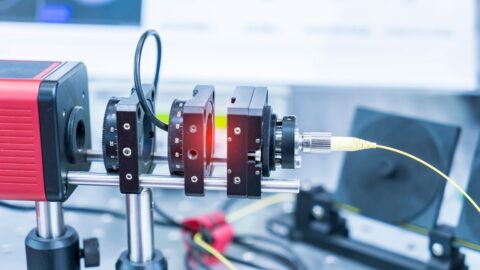
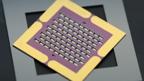
Laserline introduces a multispot optic for laser soldering and welding. The optics enable soldering or welding of materials that are difficult to process. The company deploys DC servomotors from FAULHABER to correctly distribute the energy of the different spots.
Soldering offers several advantages over welding in the automotive industry. For instance, in welding, metal sheets are heated to melting temperature along the weld seam, after which these sheets are directly joined. This requires a high degree of precision, while it is not possible to achieve welds of visible quality. In addition, welded seams are rough and porous due to evaporation of zinc.
Soldering delivers benefits
However, if soldering is chosen, metal plates are not directly joined together, but a copper-silicon solder is placed between them as a filler material. This material liquefies during soldering and then solidifies again. This not only joins the parts but also fills the gaps between them. Compared to welding, brazing therefore allows higher dimensional tolerances, while clamping workpieces requires less effort. Soldering enables gap-free joints with visible quality, so that the soldered components can be painted directly without further processing.
However, not every material is equally suitable for soldering. For example, the solder behaves differently on hot-dip galvanised metal sheets. "On the surfaces next to the seam, there was an increased number of splashes of liquid solder. Micro-spatters were particularly prevalent. These are difficult to see initially, but become clearly visible after painting," explains Dr Axel Luft, Automotive Sales Manager at Laserline. "The quality of the seam itself had also deteriorated. It was rougher and often formed so-called waves, in other words points where the solder exceeds the planned seam limit."
Thermal galvanisation
The problems are caused by the zinc layer on the metal sheet. The thermal galvanisation causes this layer to become thicker and less regular, while the material also shows a different reflection behaviour. Thorge Hammer, an engineer at Volkswagen in Wolfburg responsible for this laser process, came up with a solution. By removing the zinc from the edges of the seam before the soldering process begins, the problems can be eliminated.
In theory, this means that the usually circular laser spot for laser soldering should be made rectangular. The front corners of this spot could then be used to remove the zinc, while the rest of the rectangle would be used for the actual soldering. However, this was not technically possible. An alternative was therefore devised.
Dr Markus Baumann, chief development engineer at Laserline: "Instead of forming a spot with a complex - and therefore optically very difficult - shape, we ended up adding two smaller spots to the main spot. When soldering, these smaller spots are always focused on the edges of the seam a few square millimetres in front of the main spot." These spots are created by splitting the laser beam into three beams: a so-called homogenisation beam generates a square main spot, while two other optical elements split the beam to generate additional spots. These spots are aligned using an optical module.
Splash-free
The smaller spots provide enough energy to evaporate the zinc layer, melt the steel and generate slight oxidation. The resulting so-called 'passive layer' prevents the liquid solder from going over the edge, so no splashing occurs.
The end result is soldered parts that contain no spatter and require no further processing to be painted. An additional advantage is the more even distribution of heat over the solder than with its circular counterpart, which contributes to a quieter solder bath. "With this technology, we were finally able to solve all the problems we encountered with hot-dip galvanised metal sheets," explains Dr Luft. "It is now being used in series production at Volkswagen. And it enables us to achieve soldering speeds of up to 4.5 metres per minute. Other manufacturers will soon follow."
Setting laser power
In the case of laser soldering, two spots are generated in front of and next to the main spot. To achieve a straight seam, the power distribution between both the main and leading spots and between the leading spots themselves must be accurately adjusted. The way the laser power is distributed across the spots depends on the position of the optical elements. By moving these elements along the x- and y-axis, it is possible to fine-tune the exact distribution of laser power to specific tasks.
For example, to weld aluminium, an intensive small spotlight can be inserted into the weaker large spotlight. If metal sheets of different thicknesses need to be welded together, these spots can be adjusted to the material. This can be done during the welding process itself, as the elements in the Laserline optical modules are moved by motors.

Compact motors
These optical modules are square, with edges of 12 centimetres and a depth of 5 centimetres. This limited space houses the optical elements, as well as a sophisticated mechanical system. This meant that little space was left for the motors. The dimensions of the motors therefore played an important role in the choice.
"We chose brushless DC servomotors from the 1226 B FAULHABER series with a diameter of 12 millimetres, with guide screws fitted directly to the motor shaft and without a shaft coupling," explains Dr Baumann. "This gives us a very compact drive that still reliably delivers the required power and speed. Easy integration of the motor controller into the system was another important consideration."
RS232 or CAN bus
FAULHABER's motion controller is positioned outside the module, with communication via an RS232 serial interface. The RS232 controller can be replaced by a version with CANopen interface, which allows the motor and controller to be controlled via a CAN bus system.
The laser optic is mounted on a robotic arm, which moves the optic to the desired position. The optics must therefore withstand significant dynamic loads acting on the motors, which can cause unwanted position changes. "This is not a problem for the FAULHABER motor, as it uses its integrated Hall sensor to detect the current position and adjust it if necessary - at the latest when the laser is placed on the seam," Dr Luft states. Incorrect positioning is excluded, he says, while the motors produce consistently reproducible results.
Author: Wouter Hoeffnagel
Source: Faulhaber